When I worked for Intercrus Aero Indonesia as an aeropropulsion engineer, we were working to design an eVTOL (electric vertical take-off and landing) vehicle. This is one of the ideas proposed to overcome the congestion problem, especially in big cities or urban areas. I was responsible for the propulsion area, such as selecting the propeller, ensuring the thrust-to-weight ratio complied with the existing regulations, deciding the number of blades for our propeller, the configuration we used, etc. At least, those are some tasks I had to accomplish during my early days at Intercrus.
After several months of searching for a propeller and reaching out to so many manufacturers, I didn’t find it. We needed a 2.5 m diameter propeller with 3 blades, and this propeller had to be capable of providing a thrust of at least 1.5x the aircraft weight. To give you more context about it, our eVTOL was planned to have a 1750 kg MTOW, with 8 propellers and a coaxial configuration (so, 4 pairs of 2 stacked contra-rotating propellers). Figure 1 shows how our eVTOL (SOLA) was designed.
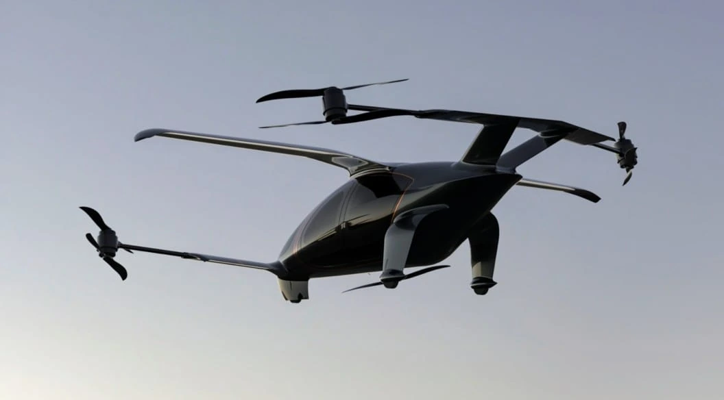
Figure 1. SOLA demonstrator V1 with 2-blade propellers.
That’s the demonstrator at 1:2 scale. For the V1 demonstrator, we planned to continue using 2-blade propellers from the MEJZLIK manufacturer at that time. But as you can see, we use 8 propellers with a coaxial configuration here. SOLA is proposed to use the propellers and the wing at the same time when it cruises. So, 60% of the lift is provided by the wing and 40% is provided by the propellers.
There are so many connected challenges during the design process. Making the propellers provide precisely 40% of the lift during cruise and also maintaining enough thrust in the x direction during forward flight (150 kph) is so hard. You cannot simply just use the following equations:
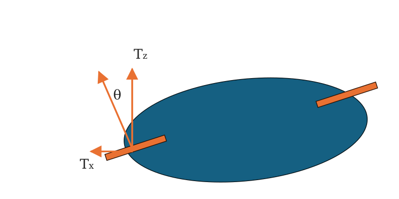
You have to consider the propeller drag (the propeller in this configuration not only produces thrust, but also drag; even each propeller azimuth position will produce different thrust and drag—the oblique loading problem). And propeller drag depends on the blade profile itself, the pitch, the twist angle, the chord, the number of blades, and the diameter. And to design an appropriate propeller, we have to know the propeller angle. Even the noise itself is also influenced by the blade profile, propeller angle, and aerodynamic interaction between the upper and lower propellers. So, we have a closed-loop problem that needs to be solved here:
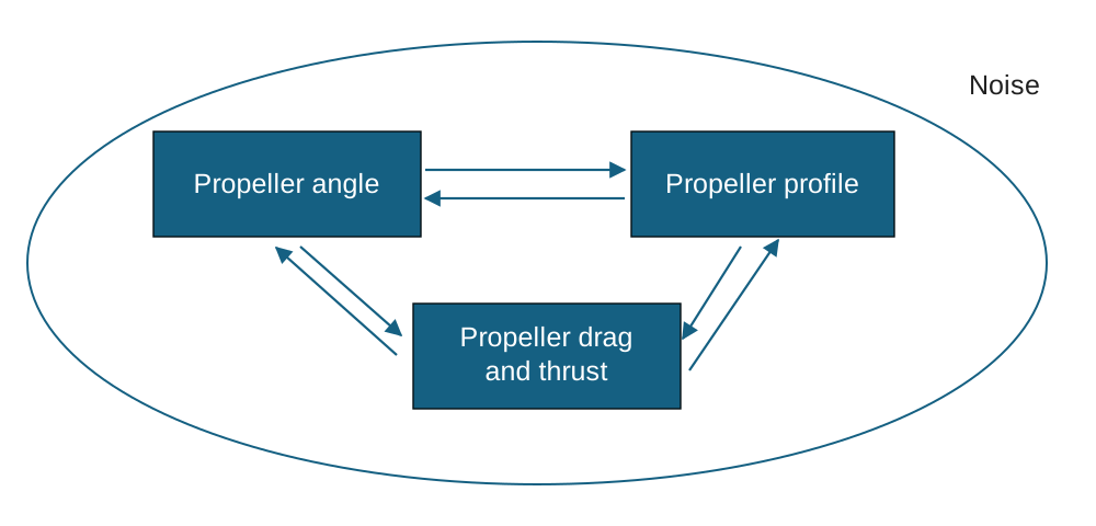
SOLA was not designed to have too high a propeller angle; 20 degrees is the maximum propeller angle. So, the rest of the work is my problem: finding the correct configuration.
The problem for the 1:2 scale is easier. Because this is only a technology demonstrator and is not proposed to fly at cruise conditions (150 kph), a 2-blade propeller for hover and 5–10 m/s forward flight was enough. So yep, we found the correct propeller for our 1:2, but we hadn’t yet found any propeller or blade design for our full scale. So, I proposed to design our own blade and propeller. This propeller had to meet several requirements, including providing a thrust-to-weight ratio (TWR) of at least 1.5 with the available motor (we ultimately achieved 1.75). The maximum power could not exceed 120 kW (we used a motor with a peak power of 120 kW, delivering 4400 N of thrust per propeller at 118 kW, with a figure of merit (FoM) of more than 0.75). It also had to be capable of continuing the flight to the nearest vertiport under an OEI condition. Furthermore, low noise was a key design consideration; the requirement was that noise levels must not exceed 65 dBA at a distance of 100 meters during a hover (a target met by the final design).
To achieve this final propeller design, I conducted numerous case studies, exploring factors such as the type of airfoil to be used, variations in blade twist angle, and propeller pitch angles. Our team at Intercrus is small; I am the sole aero-propulsion engineer, so I handled the entire propeller design process myself. I carried out dozens of case studies covering airfoil selection, blade profiles, and other parameters. Initially, we aimed for a fixed-pitch propeller. However, we encountered a significant obstacle: a fixed-pitch propeller cannot deliver optimal performance across two vastly different operating conditions—hover and cruise. Designing a propeller for high efficiency in a hover inevitably results in poor efficiency during cruise, and vice versa. After more than 100 design iterations, none could satisfy all the requirements. Consequently, we decided to adopt a variable-pitch propeller. The three blades are connected via a gear mechanism that allows their pitch angles to be adjusted simultaneously. This is a relatively simple mechanism—distinct from a helicopter’s swashplate, which can adjust blade angles based on specific azimuthal positions.
In short, the analysis and rapid design iteration were conducted in MATLAB using a program based on the work of Ege Konuk, whose software calculates propeller performance across incidence angles ranging from 0 to 90 degrees (vertical). This program was subsequently modified to suit the specific conditions of the project and integrated with research by Yong-Boon Kong on the “Development of a Finite State Coaxial Rotor Dynamic Inflow Model.” Both approaches are rooted in the dynamic inflow model originally developed by Pitt, Peters, and He.
After testing over 100 configurations, a suitable propeller design was identified, utilizing modified airfoils derived from the MH and GM series.
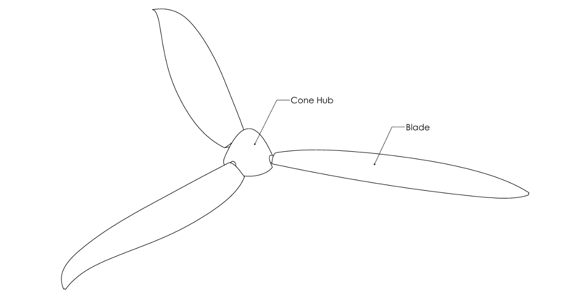
Figure 2. SOLA’s final 3-blade propeller design.
I think I can’t give you too much technical information here because this propeller has become the property of Intercrus. So I cannot expose the geometry and its calculation details here. I will create separate content, unrelated to this post, covering what a dynamic inflow model is and how it is applied. But, this propeller has results for noise, performance, and aerodynamic interaction that look something like this.
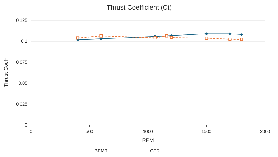
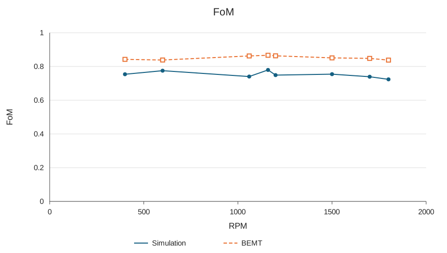
Figure 3. Thrust coefficient and figure of merit for SOLA’s propeller.
As we can see, for static conditions/hover, the performance of this propeller is considerably good. We need to accept some performance loss because we used a coaxial configuration and wanna achieve a low noise level.
The acoustic performance of the propeller was analyzed using the Large Eddy Simulation (LES) model coupled with the Ffowcs-Williams-Hawkings (FWH) acoustic analogy. The LES model was selected for its capability to resolve large-scale turbulent structures that significantly influence sound generation. In contrast, the FWH model was used to predict far-field acoustic pressure from the unsteady flow field obtained from LES.
In LES, the instantaneous velocity field is decomposed into a filtered (resolved) component and a subgrid-scale (SGS) component :
The filtered Navier-Stokes equations are expressed as:
where represents the subgrid-scale (SGS) stress tensor, which accounts for the effect of unresolved turbulent motions on the resolved scales.
In ANSYS Fluent, the Smagorinsky–Lilly model is commonly employed to approximate the SGS stresses:
with
where is the Smagorinsky constant, is the filter width, and is the strain-rate tensor of the resolved field.
The FWH equation provides the theoretical foundation for predicting acoustic radiation from unsteady flow fields. It extends Lighthill’s acoustic analogy by accounting for sound generation from moving solid boundaries and is expressed as:
where:
- is the fluctuating acoustic pressure,
- is the ambient speed of sound,
- is the Lighthill stress tensor representing quadrupole sources,
- and denote dipole and monopole source terms corresponding to surface pressure fluctuations and volume displacement,
- is the Dirac delta function locating the solid surface.
In the simulation, the FWH acoustic model was applied on a control surface enclosing the propeller to capture the near-field pressure fluctuations produced by the LES solver. The far-field noise levels were then computed using the time-dependent pressure data exported from ANSYS Fluent.
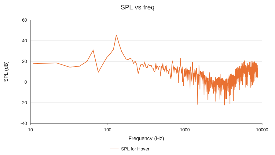
Figure 4. Propeller sound pressure level for hover conditions.
Sound Pressure Level is a standard logarithmic measure used to quantify the effective pressure of a sound wave relative to a common reference value. Expressed in decibels (dB), SPL provides a scale for the perceived loudness of a sound source. In the context of propeller performance, analyzing the SPL is essential for evaluating its acoustic characteristics and its potential impact on the surrounding environment.
The spectrum shown in Figure 4 reveals two primary components of the propeller’s noise profile. The distinct, high-amplitude peaks at the lower end of the frequency range are characteristic of tonal noise. This type of noise is generated by the periodic displacement of air as the propeller blades rotate and is often the dominant source of perceived sound. In contrast, the less structured, more random signal observed at higher frequencies is known as broadband noise. This noise is typically generated by turbulence and the shedding of vortices from the blade surfaces. A comprehensive analysis of both tonal and broadband noise is critical for developing strategies to mitigate the overall acoustic footprint of the propeller.
I mentioned earlier that a propeller with an incidence angle would experience oblique loading. The retreating and advancing blades can produce different drag, different lift, and different torque. This is what it looked like when I analysed the phenomenon using modified BEMT and a dynamic inflow model.
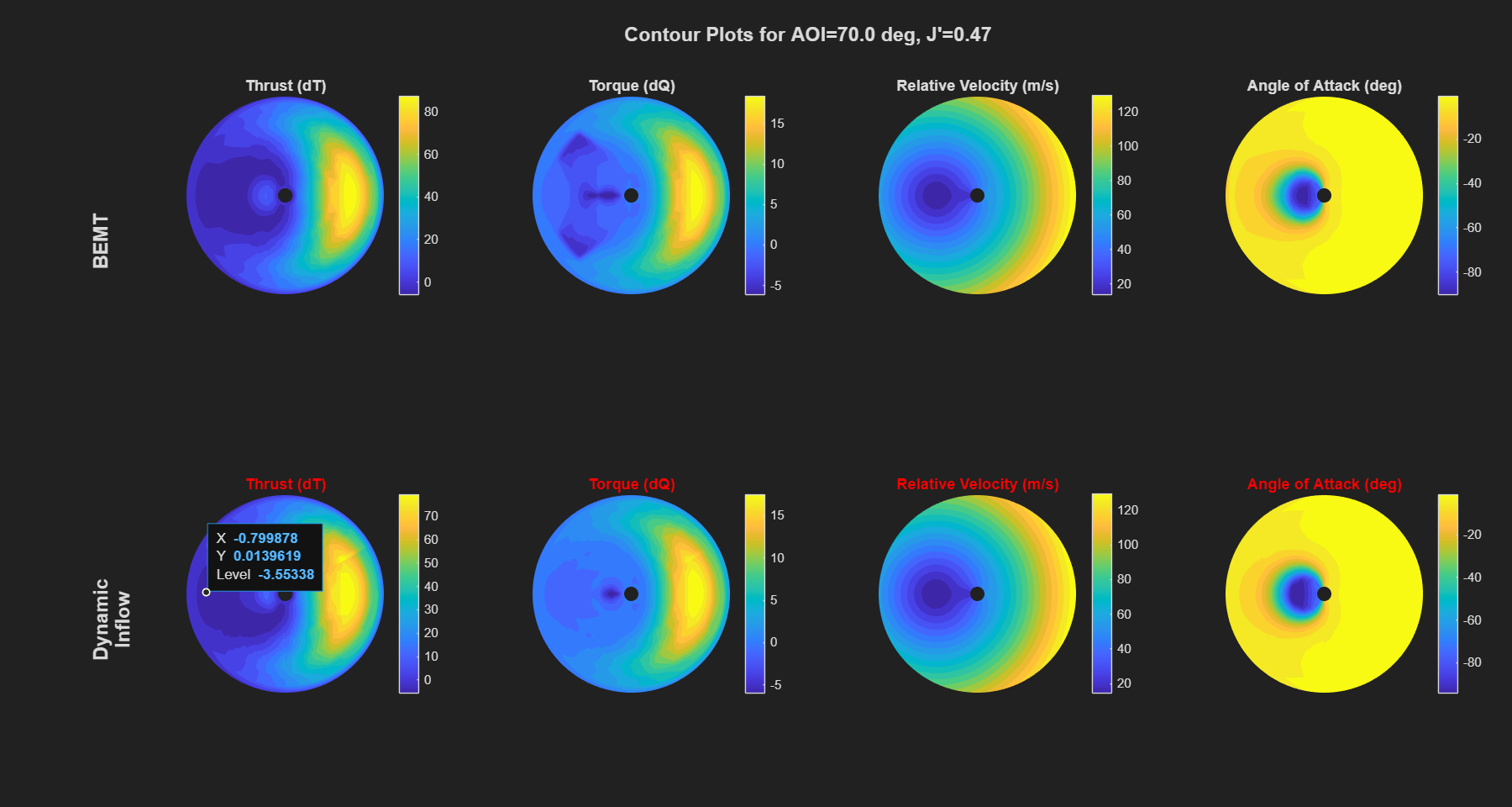
Using transient CFD, oblique loading has been analysed for the 3 individual blades, and the result is like this:
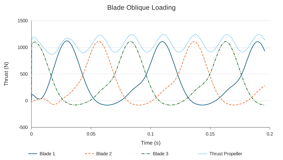
Figure 6. Oblique loading phenomena, transient sliding-mesh CFD simulation.
The propeller was simulated at 700 RPM (operational cruise RPM), angled 20 degrees from vertical (or equivalently, a 70-degree angle of incidence measured from the aircraft body axis).
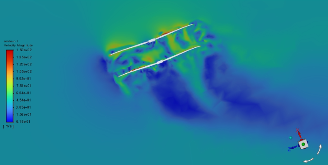
Figure 7. CFD contour.
In the end, I learned a lot from my previous job at Intercrus. Even if I only worked there for around a year, I gained a lot of knowledge, especially about industrial experiences and propeller design, and I could also contribute to building a propeller for Intercrus that then became their valuable product.