Introduction
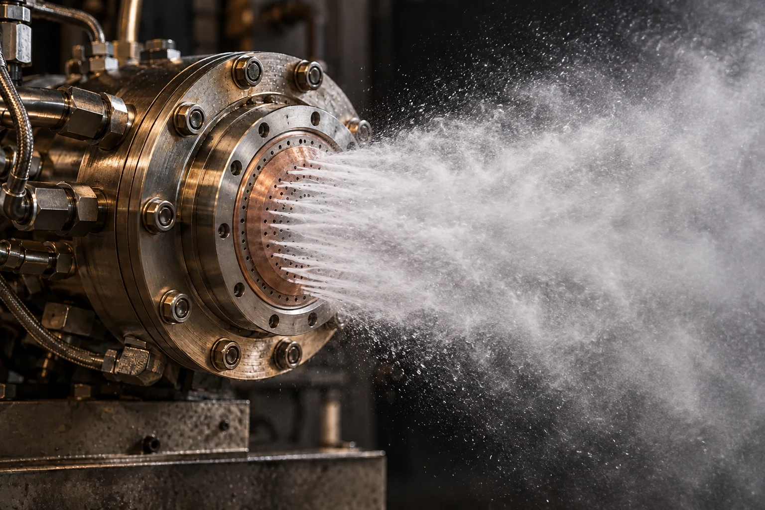
Injector is one of the main rocket components. Injector take an important part because it’s the first component faced with the combustion chamber. Bad design and 2 things would happen: 1. Cannot fire, 2. Explosion. Historically, combustion even become one of the hardest problem to solved in rocket engine. First of all, I wanna share some knowledge about this component. Injector is one of the most important components for rocket engine. Overall rocket performance is described by how well your injector design are. Injector, as the name implies, injects the propellants into the combustion chamber in the right proportions and the right conditions to yield and efficient, stable combustion process. Injector placed at the top of combustion chamber.
The injector also performs the structural task of closing off the top of combustion chamber against the high pressure and temperature contains. If you still can’t imagine how combustion looks like, just imagine an automobile’s carburator. However, the injector, located directly over the high-pressure combustion, performs many other functions related to the combustion and cooling processes and is much more important to the function of the rocket engine than the carburator is for an automobile engine. As I said before, injector is one of the most important component in the rocket engine, I think no other component of a rocket engine has a great an impact upon engine performance as the injector, not even the turbopump.
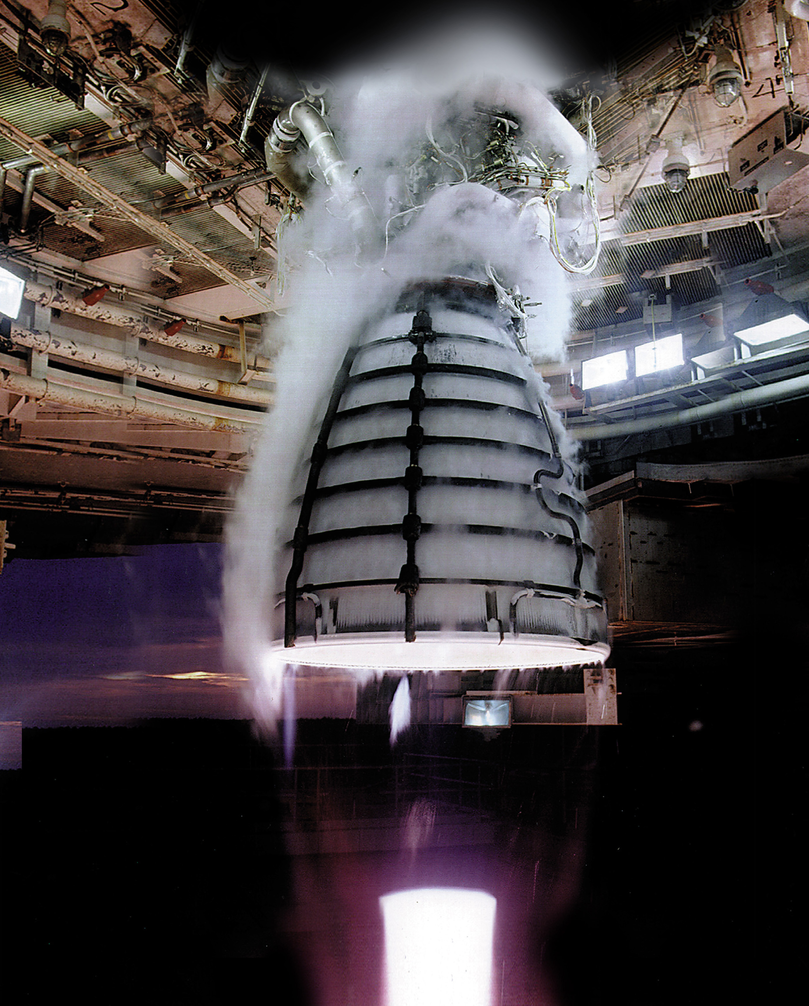
The measure of delivered performance is the number of Newton of thrust provided per kg of propellant, which then we define as a specific impulse. Each percentage loss in the injector means a loss of the same magnitude in overall specific impulse. Typically, well designed injectors may have efficiency as high as 97% or more in large engine and a small engine designed for special purpose, such as attitude control, may be optimized for response and light weight at the expense of combustion efficiency, and may be deemed very satisfactory even if the efficiency falls below 90%. Very good design injector even close to 100% in terms of efficiency, for example, SSME injector with 99.7%, and the upper stage XLR-132 engine with 99% efficiency.
High levels of combustion efficiency derive from the uniform distribution of the desired mixture ratio and fine atomization of the liquid propellants. Local mixing within the injection-element spray pattern must take place at virtually a microscopic level to ensure combustion efficiencies approaching 100% (Huzel). Injector design is very close to a problem in a liquid rocket engine called: combustion stability. High performance can become secondary if the injector is easily triggered into destructive instability. At times, it may seem that the design requirements for stability are counter to those performances, since many of the injector key parameters for high performance appear also to reduce the stability margin.
Stable operation will be depend in good part on the injection element type selected and the provision for damping any oscilatory phenomena. Injection flow resistance is an example of an aid in designing for stability; This is why, typically we design an injector within 15-25% of pressure drop.
Some Issues in Injector Design and Important Considerations
To design an injector, you have to entails many compromise. For any new engine application, there are always almost several different approaches that could produce a satisfactory injector design, and perhaps more than one approach which would provide an outstanding injector design. Lets start with the basic, if you wanna design an injector, a good starting point need to consider is the particular application, engine size, propellant combination, and design priorities. Of course, the initial approach invokes complete optimization of all feature: light weight, high performance, low cost, reliability, manufacturability, etc. But that soon emphasizes priority for the very important design params. For instance, let’s take a look into SSME, RS-25.
This legendary engine was used for a highly sophicticated, high-performance booster using hidrolox propellants. It designed to be reusable over multiple missions in manned spacecraft, a use that dictates a higher reliability than any other aspects. SSME actually has three injectors: the usual main-engine injector, and one injector each for the fuel and oxid turbine-drive preburners. Each had to be highly optimized for its specific task. That’s why shear coaxial injector has been used for this engine. Anotherexample, what if your main objective is for a “small kinetic-energy” weapon? This engine had a firing life only a few second but had to reach thrust in a handful of milliseconds. The injector such as unlike impinging may be the best option.
You can build it with a short direct passages manifold from a valve and directly integrated to the injector body. You may need several injector, 9, 18, or 36 element pattern. We also distinguish different injector type by the type of propellants used in the engine. For hidrolox (liquid ocygen and lightweight liquid hydrogen), a coaxial element will be the primary candidate. For hypergolic liquids and rapid response in a small chamber, an unlike-impinging pattern will be a good starting point. You might also curious, for a large booster with LOX/RP-1 propellants, what types of injector we need to use? Well, the major issue in a large engine is the combustion stability.
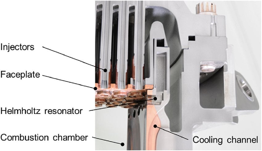
Moreover, with LOX/RP-1 propellants, the density of the fuel and oxidizer is quite different and rules out the use of a coaxial pattern. So, the best choice would probably like-doublet impinging injector. And so on. You can continue the engineering decision process by following the same rules. Another important design parameter is mass distribution. For successful injector design, the interaction of oxidizer and fuel inside the combustion chamber need to be uniform. But, uniformity here is truly hard to achieve. The mechanical space requirements for the perimeter of the manifolds push the outer row of elements inward, away from the wall. In addition, the use of acoustic cavities (Helmholtz resonator) around the injector perimeter further forces the outer row away from the wall.
The result usually will be a mass deficient zone around the injector perimeter. The initial gas generated, centered, inward, will tend to fill the chamber area, causing an outward radial wind that caries a portion of the reacting gasses against the wall. With most liquid propellant combinations, the oxidizer-rich hot gases thus scrub the upper section of the chamber severely, increasing local heating, and, in extreme cases, burning the inner surface of the chamber. That’s why, we also need to consider mass distribution in the combustion chamber to avoid catastrophic failures. Mixture ratio distribution also plays an important part from the standpoint of both performance and chamber compatibility.
With combustion chambers materials (copper, nickel, steel), it can be a fuel and is important to avoid that. The interaction between high temperature oxidizer rich environment and any of these metals can scrubbing the chamber wall. Most injection patterns are designed to avoid this possibility, and generally to provide an excess of fuel in these areas. We usually use film cooling technique to create a boundary layer cooling system made of fuel that directly impinge against the wall at a shallow angle, to spread a protective evaporating layer on the wall surface. Other systems use “barrier zone” elements, either fuel-rich or totally fuel, in the region adjacent to the wall.
All these methods involve a performance penalty, since the coolant fuel mainly will be unavailable for effective combustion. It will not be completely lost from the propulsive flow, however, because it will be heated and expanded as part of the working fluid; but this is less effective than burning it in a well-mixed fashion. The performance loss is significantly depends on the fuel type.
Combustion Stability
As mentioned previously, high performance can become secondary if the system can easily be triggered into a destructive instability, and many of the injector parameters that provide high performance appear to reduce stability margin. All systems which release large amount of energy have the potential for destructive oscillations, particularly if there is regenerative feedback gain between the combustion phenomena and the pressure variations. Why did it happened? Yeah, you have to think about the pressure and temperature oscillation, as long as the reaction within it. Pressure, temperature, and reaction rate are highly related each other and as I said before, these parameters has feedback gain interaction.
Oscillation on pressure means oscillation on temperature means oscillation on reaction rate, reaction rate dictate the pressure and temperature and so on. The next question is, what really affect this combustion stability? First of all, you have to know that each injector has its own characteristic, it also applied to how the injector affect the combustion stability. In general, unlike-impinging elements are the most easily excited to instability, with like-impinging elements lower in sensitivity, and non-impinging like coaxial swirl etc is the most stable.
Combustion and Structural Stability Interaction
Moreover, if we talk about combustion stability, we can’t ignore the interaction between fluid and the structure of the rocket itself. Manifold is a component that so close to the injector so that the interaction between the instability and manifold is quite strong. Manifold may have frequency characteristics that can couple with chamber acoustic modes. This fluid-structured interaction phenomena can easily become larger and larger and then causing some crack in the engine forward closure. One example of this, the length of the central post in a coaxial injection element, can have organ-pipe mode that can exist in ring-groove manifolds. These frequencies should be considered during design, and damping devices or detuning applied where appropriate.
To overcome this problem, injectors frequently have physical devices to aid in damping or to otherwise change frequency response. Some technique like adding baffles on the injector face or adding acoustic cavities can reduce this interaction. For example, baffles reduce the effective local size of the combustion area by compartmenting the injector face, thus raising the resonant frequencies to higher, more easily damped, values. But remember that the baffles operate in a high-heat-load environment, and cooling provisions is needed. The length of the baffles are also related to energy release rates, which describe the so-called sensitive zone, the zone where the region most likely to initiate instability.
On the other hand, acoustic cavities are damping devices that employ tuned length or other open areas exposed to the reaction process. We called this device as Helmholtz resonators (as shown in Figure 2).
Types of Rocket Injector
Now after you know the whole story about injector, the challenge have to faced, some introduction about types of injector, we can move further and deep dive into types of rocket injector.
1. Showerhead Injectors
This is the easiest type to imagine. Fuel and oxidizer are injected through many small holes mostly parallel to the chamber axis. There is no intentional jet-to-jet impingement at the injector face. The streams break up and mix downstream because of turbulence, aerodynamic shear, droplet breakup, and the interaction with the surrounding droplet and gas.
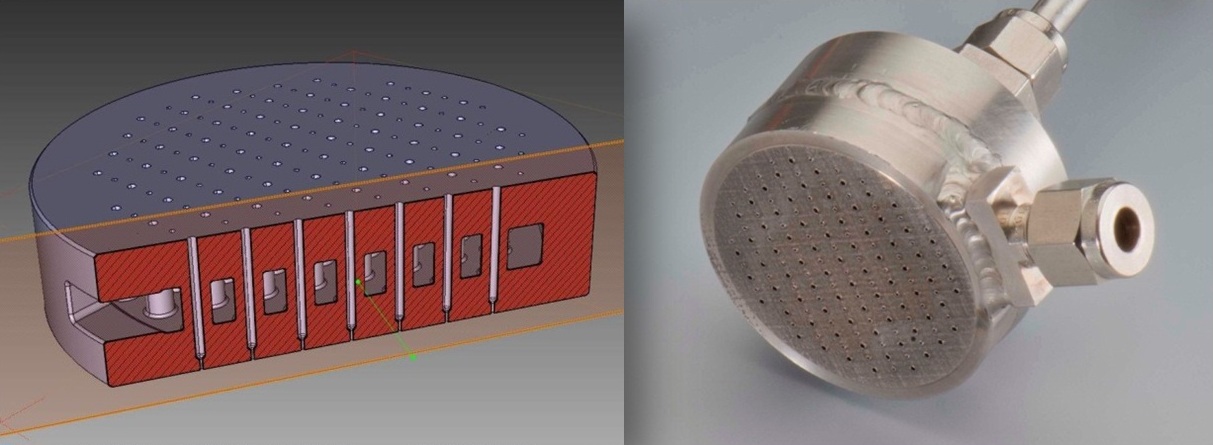
The main advantage is simplicity. The passages can be easy to manufacture and the face pattern is easy to understand. The disadvantage is that you do not get the very rapid geometric mixing produced by direct impingement. That can increase the required mixing or combustion length. Showerhead patterns are also sensitive to how uniformly the manifolds feed every hole; a simple pattern does not automatically mean a uniform pattern. For monopropellant thrusters the word “showerhead” can also describe a distributor that sends propellant into a catalyst bed. In that case, uniform distribution over the catalyst face becomes more important than fuel-oxidizer mixing.
2. Impinging Injectors
Impinging injectors deliberately collide liquid jets. The collision converts the two cylindrical jets into a thin liquid sheet or spray fan. Because the liquid is suddenly redirected and stretched, atomization and mixing can be very fast. The important parameters are orifice diameter, injection velocity, impingement angle, impingement distance, momentum ratio, element spacing, and orientation.
2.1. Unlike Dublet
In an unlike doublet, one fuel jet and one oxidizer jet collide. This gives direct fuel-oxidizer contact immediately after impingement, so it can give excellent mixing in a short distance. This is particularly attractive for hypergolic propellants, but the same rapid reaction that gives fast ignition can also make the element dynamically sensitive. If reaction begins essentially at the impingement point, the injector face sits very close to the energy-release zone.
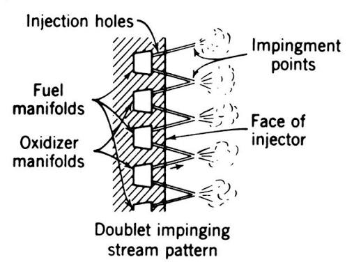
The spray direction is controlled by the vector sum of the incoming jet momenta. If the two jets do not have balanced transverse momentum, the resulting sheet will be pushed toward one side. This is why “same hole diameter” is not enough when the two propellants have different density or mass flow.
2.2. Like Doublet
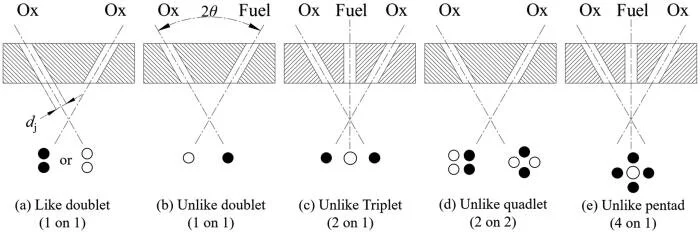
In a like doublet, two jets of the same propellant impinge first. The collision forms a sheet of fuel or a sheet of oxidizer; that sheet then mixes with a neighboring sheet of the other propellant.So like doublet collide fuel-fuel or oxidizer-oxidizer sheet. Compared with an unlike doublet, the initial atomization and the initial chemical mixing are partly separated. That can be useful when you want good atomization but do not want the reaction zone attached too aggressively to the injector face. Like-on-like patterns can also give the designer more freedom to arrange fuel-rich barrier regions near the chamber wall. The tradeoff is that the complete injector pattern becomes more complicated because the separate fuel and oxidizer sheets still have to overlap correctly downstream.
There are also 3 other types of impinging injector like: Triplet, Quadplet, and Pentad. Here is the full comparison of these 5 impinging injectors.
3. Splash-Plate or Target Injector
A splash-plate injector directs one or more liquid jets onto a solid target or deflector. The target converts the jet into a sheet and breaks it into droplets. It is mechanically intuitive
and can create strong atomization, but now the target itself lives in a severe thermal and mechanical environment. The solid surface can also introduce additional heat transfer, erosion, coking, or durability problems depending on the propellant. This type is less common in modern high-performance main chambers, but it is still useful to understand because it makes one idea very clear: atomization does not have to come from jet-to-jet collision. It can also come from jet-to-solid interaction.
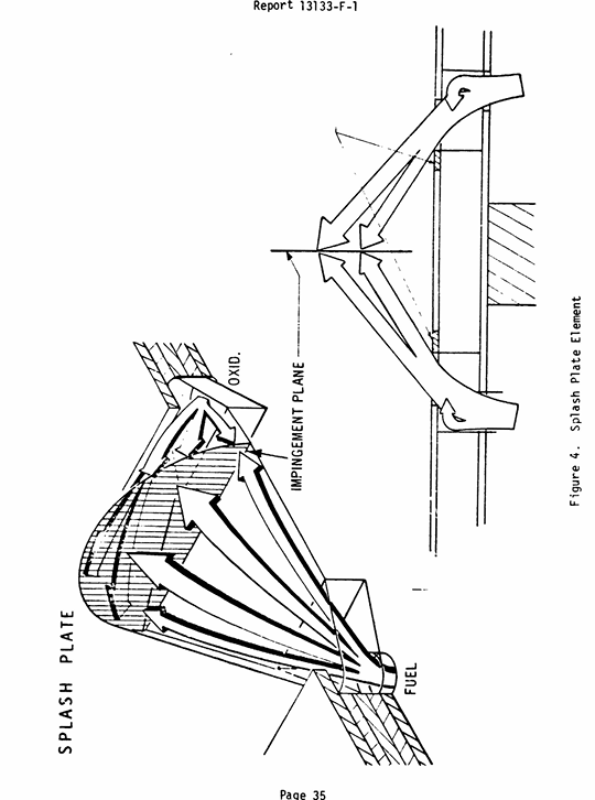
Splash-plate injector has been used in many application, including the early versions of the Lance booster engine and Gemini manu evering engine. These elements have been used extensively at low thrust level in production thrust chamber assemblies where the total number of orifices was very small, primarily to improve ablative wall durability and sencodarily to reduce variations in performance induced by inadequate injector hydraulic control. This type of injector also has very simple injector manifold system.
4. Shear Coaxial Injector
This is one of the most important injector families for liquid rocket engines. Imagine a tube inside another tube. One propellant exits through the center post, while the otherexits through the surrounding annulus. The streams are almost parallel, so there is no violent geometric impingement. Instead, mixing is driven by velocity difference and shear at the interface. For a typical LOX/GH2 element, the dense oxygen stream can leave from the center while the high -velocity hydrogen-rich stream flows around it. The gas strips waves and droplets from the liquid core. The stronger the relative velocity and aerodynamic force, the faster the liquid core breaks up. This is why velocity ratio, momentum -flux ratio, post thickness, recess, and annulus gap become key design parameters.
The advantage is that the heat -release zone can be distributed farther downstream, which can reduce local injector -face heating. The disadvantage is that slower mixing may require more chamber length. Also, the center post itself can behave acoustically li ke a small pipe, so post length and recess can influence stability.
Because of its high performance, ease of fabrication, and uniform combustion characteristics, shear coaxial injector gained a well -earned reputation as a high performance, stable injection element for gaseous fuel and liquid oxidizer and was extensively used in rocket industry . They have been widely used in staged combustion cycle engines mainly using LOX/H2 such as Vulcain engine for Ariane 5, RD -0120 for the Energia launcher and the SSME. Another disadvantages (forgot to mentioned before) is that shear coaxial injector is sensitive to pressure drop pulsation. You might realize something, this injector mainly working by utilize the shear phenomenon. To get high shear interaction, we need a difference between the gaseous fuel and liquid oxidizer to work well.
Unfortunately, it is less well suited to liquid fuels or even very dense gaseous fuel since the velocity difference relationship required to make it work is so difficult to achieve, which result in low combustion efficiency. However, in history, very fine elements in shear coaxial injector can produce up to 95% efficiency in liquid/liquid propellant form. For instance, LOX/JP4 and N2H4/NTO.
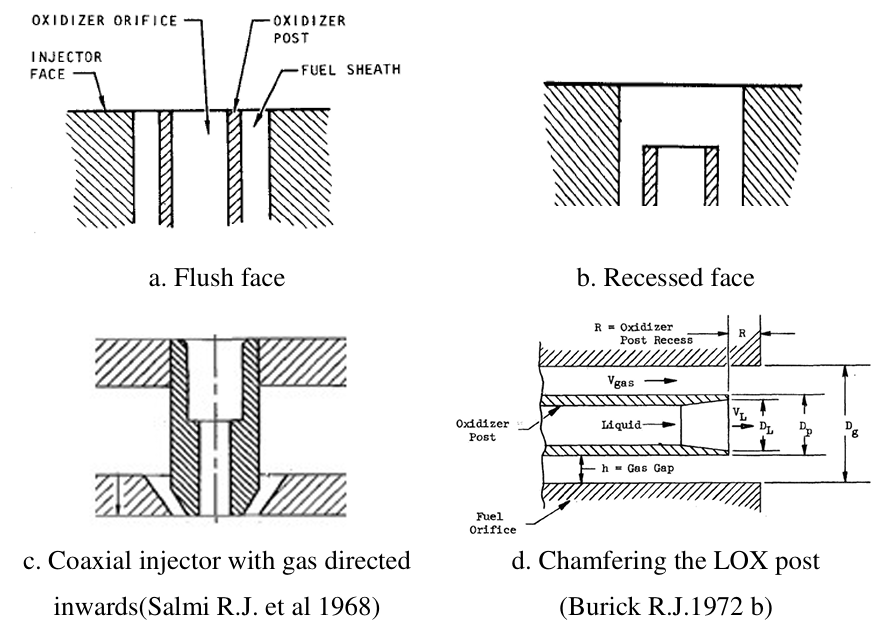
Figure 7 shows the various types of concentric tube elements have been built. For J-2 engine, recessing te element result in reduction of self -triggering temperature with 2% increase in combustion performance (Tomaizc et al. 1968). However, it appears that large thrust -per-element coaxial injectors are more sensitive to oxidizer post recess than small-thrust per element coaxial injectors. I will discuss about this type of injector in the next post, such as: the breakup regimes, Rayleigh break up, etc. This post is for some general and “quite basic” knowledge about all types of injectors.
5. Swirl Injectors
Swirl injectors are known for their superior atomization and mixing characteristics while achieving stable combustion in rocket engine. A swirl injector deliberately gives the propellant tangential velocity before it exits. Instead of leaving as a solid cylindrical jet, the liquid tends to form a rotating annular sheet and then opens into a hollow or partially filled cone. The sheet can
become very thin, so it can atomize efficiently. Swirled flow produce a compact breakup length in cold flow test, a compact flame in hot test. Compared to jet injectors, swirl injectors in liquid propellant rocket engines distinguish themselves in several aspects. First, There are several variations. A single-fluid pressure-swirl element may use tangential entry ports feeding a small swirl chamber. the intra-element mixing is significantly improved because of the outward spreading of the liquid spray. High mixing efficiency is, thus, possible even for a large injector flow rate. Second, the large flow passage in a swirl injector renders the atomizati on characteristics to be less sensitive to manufacturing errors.
Third; the resultant mean diameter of droplets is 2.2 to 2.5 times smaller than that produced by a jet injector with the same pressure drop and mass flow rate. The droplet size distribution is also more uniform. There are several types of swirl injectors. Start from single swirl injector. Single swirl injectors are often reffered to as a simplex or pressure-swirl atomizer. The single swirl injectors create angular momentum by injecting the liquid tangential into a vortex chamber then forms a swirl film attached to the wall due to centrifugal force. A hollow gas core exists in the center region in accordance with the conservation of angular momentum. If you can’t imagine, then look at Figure 8.
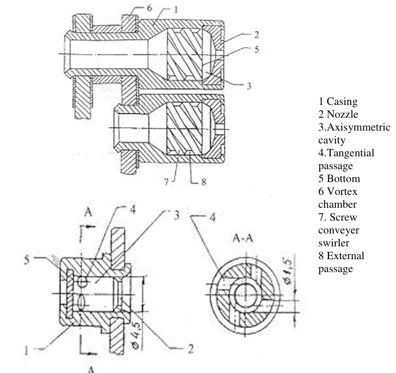
As you can see, the swirl chamber usually contracts near its exist and then straightens out again to form a finite length orifice. After the fluid out from the orifice, Kelvin -Helmholtz instability emerges in the liquid sheet, and, subsequently, leads to sheet breakup and droplet formation. Also, you can see we have 2 types here, up swirl insert and down tangential inlets. Both ha ve its own advantages and disadvantages. Up swirl insert is simpler, wit h smaller space for each injector, but less effective than tangential inlets. It usually use d in a low -flow to minim ize the vortex chamber volume. I will explain with detailed explanation about this injector in the next post. This is only for a brief introduction.
6. Gas/Liquid swirl coaxial injectors
Haha this is my favourite one. The main motivation to consider gas/liquid injector, is the wide increase usage of staged combustion cycle which uses combustion gases (from the preburner)
and liquid propellant as the propellant combination in the main combustion chamber. The atomization happened by a combination of two factors: the tendency of the conical sheet to disintegrate as It swirls and stretches and the tendency of the coaxial gas flow to accelerate sheet breakup due to its momentum transfer to conical sheet. Disadvantage of this injector type are in its more complicated design, manufacturing, and its ability -if not properly designed -to form strong self oscillation. Swirl coaxial injectors has been successfully employed for decades in the RL10A rocket engine system.
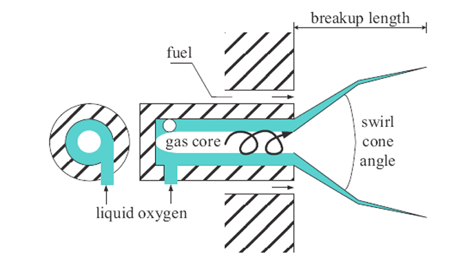
In comparison, with equivalent geometry shear coaxial injectors the swirl coaxial injector has much better performance than shear coaxial (95% compared to 85%). This indicates that the atomization/combustion process is less efficient in shear coaxial injector and for swirl coaxial, the injector with higher momentum ratio have better atomization. When considering combustion stability; for swirl coaxial injector, the liquid stream is guarded by the high momentum fuel stream, which minimizes the effect of disturbance outside the stream on atomization, mixing and combustion processes, resulting in good combustion stability. But there’s also one thing need to consider before we start to use this type of injector. The momentum ratio.
The spreading angle ofc is higher for the swirl injector with low momentum ratio. However, as increasing gas/liquid momentum ratio (rich fuel combustion with very high momentum ratio like in SSME preburner), the spreading angle of shear coaxial injector and swirl coaxial injector is similar. This had been studied by researches in space shuttle program. When SSME encounter a problem of uneven temperature distribution in exit of preburner which deterioriate turbine performance, researcher have an idea to adding swirl to the original shear coaxial injector to increase spreading angle hence better mixing. But, the experiments proved no enhancement. Spreading angle decrease as gas momentum opposes the outward expansion of the liquid sheet, this make a large spreading angle also hard to develop.
7. Bi-swirl coaxial injector
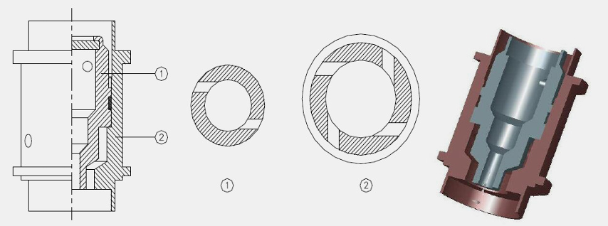
A bi-centrifugal swirl injector consists of an inner simplex injector and an outer swirler. In the bi-centrifugal swirler, fluid is injected tangentially into both the inner and outer swirl chamber. The swirling fluids proceed down the length of the swirl chamber, and then coalesce into a single
hollow cone if their trajectories intersect. The difference between the inner and outer swirler is the absence of a gas core for the outer swirler. Bi-centrifugal swirl injectors are used extensively in the Russian rocket program. In addition to the possibility of high thrust per element, these injector types features a wider range of throttle -ability, an increased margin from combustion instability, and reduced pressure drop through the injector which can result in a deceased demand on rocket turbo machinery. It also been used by space X rocket engine, raptor.
8. Pintle injectors
I think pintle injector is unique compared to other injectors. In a bi-propellant engine, one of the propellant flows down the inside the pintle and is ejected radially through a series of holes or slots near the tip of the pintle. The other propellant leaves the manifold through an annular sheet around the base of propellant.
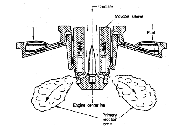
Pintle injectors enjoy several advantages first; the design is inherently simpler in the sense that only a single injector element is required which made pintle injector simpler to build. Second advantage is the inherent combustion stability afforded by this injector. There has never been an
instance of combustion instability associated with pintle engines. Third attractive feature involve its throttle-ability. Throttling ratio of 20:1 has been demonstrated with hypergolic propellants.
Governing Equations for Injector Design
Now we go to the equations. I do not wanna put equations here just to make the article look “technical. ” Each equation below answers a specific design question. Most of them are first-order equations, which means they are excellent for sizing and understanding trends, but they do not replace cold-flow testing, high-frequency instrumentation, CFD, or hot-fire testing.
1. Mixture Ratio
This is the global oxidizer-to-fuel mass-flow ratio. If the engine requires O/F = 2.8 and the total flow is known, this equation immediately fixes the oxidizer and fuel mass flows. The same idea can be applied locally to an injector element or to a small region of the injector face. A globally correct O/F does not guarantee a locally correct O/F.
2. Injector Pressure Drop
The injector pressure drop is the pressure available to accelerate the propellant through the injector passages. This is also one of the major knobs for dynamic isolation. A very small ΔP gives low pumping loss, but chamber-pressure oscillations can more easily modulate the injection flow. A larger ΔP usually makes the injector hydraulically “stiffer,” but it costs feed-system pressure and pump power.
This nondimensional pressure-drop ratio is convenient when comparing engines at different chamber pressures. Historical designs often use injector pressure drops that are a meaningful fraction of chamber pressure, but the correct value is not universally 15–25%. It depends on propellant state, injector type, stability margin, feed-system architecture, and available pump or tank pressure.
3. Liquid-Orifice Mass Flow and Orifice Area
For single-phase incompressible flow through an injector orifice, this is the basic sizing equation. C_d is the discharge coefficient, A is the effective flow area, ρ is density, and ΔP is the injector pressure drop. This equation is simple, but C_d contains a lot of real geometry: inlet rounding, length-to-diameter ratio, surface roughness, contraction, cavitation, and manufacturing tolerance.
This is Equation (4) rearranged for design. Once you know the required mass flow per element, density, pressure drop, and an estimated discharge coefficient, you can calculate the required total orifice area. From there you choose the number of holes and each hole diameter.
The injection velocity matters because atomization and mixing depend strongly on momentum. For the same ΔP, a low-density fluid reaches a higher ideal velocity than a high-density fluid. This is one reason gas/liquid coaxial injectors can have extremely large velocity ratios. For cryogenic propellants near saturation, flashing or two-phase flow can make the incompressible orifice equation inaccurate. In that condition you need a two-phase critical-flow model or real-fluid CFD instead of forcing Equation (4) to fit the data.
4. Why Pressure Drop Helps Isolate Chamber Oscillation
This is one of the most useful small derivations in injector design. Start from the orifice equation and assume manifold pressure is approximately constant over one high-frequency chamber oscillation. Because ΔP = P_manifold − P_c, a chamber-pressure perturbation changes injector ΔP.
The important part is the denominator. If ΔP_inj is small, the same chamber-pressure oscillation produces a large percentage change in injection flow. If ΔP_inj is larger, the injector flow is less sensitive. This is the mathematical reason injector pressure drop can improve dynamic isolation. It does not guarantee stability, but it reduces one feedback path between chamber pressure and propellant flow.
5. Characteristic Velocity and Combustion Efficiency
Characteristic velocity c* is mainly a combustion-performance quantity. It removes most of the nozzle-expansion effect and tells us how effectively the chamber converts propellant chemical energy into high-temperature gas. A_t is nozzle throat area.
This is the characteristic-velocity efficiency. For injector work, this is usually more meaningful than looking only at thrust or Isp, because it isolates the combustion side of the engine. Poor atomization, poor mixing, wall-film losses, or incomplete reaction can all reduce η_c*.
6. Momentum and Impingement
This is the momentum rate of one jet. For an impinging element, it is often more useful than velocity alone. Two jets with the same velocity can have very different ability to deflect the spray if their mass flow rates are different.
The spray sheet leaves approximately in the direction of the resultant momentum vector, before aerodynamic and combustion forces reshape it. For a symmetric doublet, the transverse momentum components should balance. For an unlike element, that usually requires different orifice areas or velocities for fuel and oxidizer.
This momentum-rate ratio is a simple way to compare the two impinging streams. Different injector correlations define momentum ratios differently, so always state the convention you use. The main engineering point is that spray direction and penetration depend on momentum balance, not only on geometric impingement angle.
7. Coaxial Mixing: Velocity Ratio and Momentum-Flux Ratio
For a gas/liquid shear coaxial element, velocity ratio is a first indicator of how aggressively the gas can strip the liquid core. A larger relative velocity generally strengthens interfacial waves and breakup, although geometry and density still matter.
J is the momentum-flux ratio. It compares dynamic pressure or momentum flux of the two streams. In a coaxial injector, VR can be very large while J remains moderate because the gas density is much lower than the liquid density. This is why both quantities are useful.
8. Atomization: Reynolds, Weber, and Ohnesorge Numbers
Reynolds number compares inertial force to viscous force. Large Re means viscosity has less ability to keep the jet smooth. Injector flows are usually highly inertial, but viscosity still matters strongly for very small passages or very viscous fuels.
Weber number compares aerodynamic/inertial force to surface tension. For a liquid jet exposed to a fast gas stream, U_rel is the relative velocity between gas and liquid. As We increases, surface tension becomes less able to hold the jet together and breakup becomes easier.
Ohnesorge number compares viscous effects to the combined effects of inertia and surface tension. Re, We, and Oh together help identify the breakup regime. They do not directly give one universal droplet diameter, but they tell you which physics controls the atomization.
9. Droplet Evaporation and Combustion Delay
This is the classical d-squared evaporation law. It says the square of droplet diameter decreases approximately linearly with time under idealized quasi-steady evaporation. K is an evaporation constant that depends on gas temperature, pressure, transport properties, and composition.
The important stability connection is here: larger droplets live longer. Atomization therefore changes not only combustion efficiency but also the time delay between injection and heat release. That time delay can determine whether heat release damps a pressure wave or reinforces it.
10. Swirl Number
Swirl number compares axial flux of angular momentum with axial momentum. Larger S means stronger rotational motion relative to straight-through motion. Strong swirl can widen the spray and create recirculation, which can accelerate mixing, but it can also move hot reaction zones or droplets toward the wall. For real injector design, geometry-based swirl correlations are often used, but this definition explains what swirl physically means.
11. Pintle Momentum Parameters
For a pintle, the two main streams are often approximately radial and axial. The total momentum ratio, TMR, describes which stream dominates the final spray direction. Some references use the inverse definition, so again the convention must be stated.
The blockage factor describes how much of the pintle circumference is occupied by radial slots or flow openings. It influences how continuous or segmented the radial sheet becomes.
An effective momentum ratio can combine the global momentum balance with the geometric blockage. This helps correlate pintle spray angle and penetration, but it is still an empirical design parameter rather than a fundamental law.
12. Chamber Characteristic Length and Residence Time
Characteristic length L* connects chamber volume with throat area. It is not an injector equation by itself, but it tells you how much chamber volume is available for atomization, vaporization, mixing, and reaction. An injector that mixes slowly usually needs more effective combustion length or volume than one that mixes very rapidly.
This crude residence-time estimate gives another way to compare the time available for combustion with atomization, evaporation, and chemical time scales. If the total combustion delay becomes too large relative to the residence time, c* efficiency falls. If the delay aligns badly with chamber acoustics, stability can also become worse.
Mass Distribution and Mixture-Ratio Distribution
Another important design parameter is mass distribution. For a successful injector, the mass flux should be distributed intentionally across the chamber cross-section. “Uniform” does not always mean literally identical everywhere. Near the wall, we may intentionally bias the distribution fuel-rich for thermal protection. The important thing is that the distribution is known and compatible with chamber cooling and combustion. Mechanical space around manifolds, seals, bolts, igniter passages, baffles, and acoustic cavities can push the outer row of elements inward. The result can be a mass-deficient zone near the wall. Gas generated in the denser central region then expands radially outward. If that radial flow carries an oxidizer-rich hot mixture toward a metal wall, local heat flux and oxidation can increase dramatically.
A simple way to visualize injector mass distribution is local mass flux, G. During a cold-flow test, the injector face can be divided into collection cells. The measured flow in each cell divided by the cell area gives a mass-flux map. This is much more informative than knowing only the total flow rate.
The local mixture ratio map should be examined together with the mass-flux map. A region can have the correct total mass flux but still be dangerously oxidizer-rich. This is why mass distribution and mixture-ratio distribution are related but not identical problems. With chamber materials such as copper alloys, nickel alloys, or steels, local oxidizer-rich hot gas can become a serious compatibility problem. Most injector patterns therefore avoid strongly oxidizer-rich regions near the wall. A common method is to use fuel-rich barrier elements or dedicated film cooling. The performance penalty comes from the fact that some fuel is used primarily as coolant and does not burn at the optimum mixture ratio, but that penalty is often much cheaper than losing the chamber wall.
Combustion Stability
As mentioned previously, high performance can become secondary if the system can easily be triggered into destructive instability. A rocket chamber contains a huge rate of energy release inside a small volume, so even a small oscillation can become dangerous if the heat-release fluctuation gives acoustic energy back to the pressure wave at the right phase. The first thing to separate is frequency range. Low-frequency instability such as chug is often strongly connected to feed-system compliance, injector pressure drop, phase change, and combustion time delay. Intermediate-frequency “buzz” can involve injection or chamber longitudinal dynamics.
High-frequency instability or screech is usually connected more directly with chamber acoustic modes such as tangential, radial, or longitudinal modes. These names are useful, but the actual boundaries are engine-dependent.
The Acoustic Wave Equation
This is the linear acoustic wave equation for pressure perturbation p′ in an ideal uniform medium. It tells us that the chamber can support natural pressure-wave shapes, just like an organ pipe or drum. The chamber geometry determines the mode shapes; the hot-gas speed of sound sets the frequency scale.
This ideal-gas expression shows why chamber acoustic frequency changes with gas temperature and composition. Hotter gas generally has a higher speed of sound, so the same chamber geometry resonates at a higher frequency. In a real rocket chamber, γ and R vary with composition and temperature, so equilibrium or frozen-gas properties may be used instead of one constant value.
Ideal Cylindrical Chamber Modes
This is an idealized acoustic-mode equation for a rigid cylindrical chamber. R is chamber radius, L is acoustic length, q is the longitudinal mode index, and α′_mn is a root related to the radial/tangential Bessel-function mode shape. For a pure first longitudinal mode, the transverse term is zero and the familiar approximation f ≈ a/(2L) appears. For transverse modes, chamber diameter becomes the dominant geometric scale. Useful roots for the ideal rigid cylinder are approximately α′₁₁ = 1.841 for the first tangential family, α′₂₁ = 3.054 for the second tangential family, and α′₀₁ = 3.832 for the first radial family. These are starting estimates only. The injector face, nozzle, mean flow, cavities, baffles, temperature gradients, and non-cylindrical geometry shift the real frequencies.
Rayleigh Criterion: When Does the Oscillation Grow?
This is the core idea behind combustion-acoustic coupling. p′ is pressure fluctuation and q̇′ is heat-release-rate fluctuation. If their cycle-averaged product is positive and larger than the acoustic losses, combustion adds energy to the acoustic field and the oscillation can grow. If heat release tends to occur when pressure is low, the integral can become negative and the combustion process damps the wave. So the problem is not simply “pressure oscillates, therefore temperature oscillates. ” The dangerous condition is phase coupling. You need pressure and heat-release oscillations to line up in a way that gives net acoustic energy back to the chamber.
Combustion Time Lag
A simple time-lag model says the unsteady heat release responds to a pressure or injection disturbance after a delay τ. The interaction index n represents how sensitive combustion is to that disturbance. This is a simplified model, but it explains why atomization and evaporation time matter so much for stability.
If the pressure oscillates at angular frequency ω, changing the combustion delay τ changes the phase between pressure and heat release. A design change that barely affects steady c* can therefore move the system from damping to driving if it changes τ enough. This is one reason injector recess, droplet size, mixing length, and propellant temperature can affect stability unexpectedly.
Injector-Feed-System Coupling and Chugging
The chamber is not isolated from the tanks, pumps, valves, and manifolds. The feed system has inertia and compliance, while the injector acts like a hydraulic resistance. Together they form a dynamic system that can have its own natural frequencies.
Hydraulic inertance L_h represents the pressure required to accelerate fluid in a line or passage. A long, narrow, dense-liquid line has large inertance.
Hydraulic compliance C_h represents how much fluid volume can change with pressure. Compressible gas volumes, flexible structures, cavitation, or two-phase regions can increase effective compliance dramatically.
This is the simplest inertance-compliance resonance estimate. Real feed systems have many distributed modes, but this equation gives the physical picture. If a feed or manifold mode lies near a combustion-response frequency, mass-flow oscillations can couple with chamber pressure and produce chugging or injection-coupled instability.
For an orifice with ΔP proportional to Q², the incremental hydraulic resistance increases with pressure drop. This is another way to see why a higher injector pressure drop can add dynamic isolation and damping between chamber and upstream manifolds.
Combustion and Structural Stability Interaction
Moreover, if we talk about combustion stability, we cannot ignore the structure of the engine itself. The manifold, injector face, injector posts, forward closure, chamber wall, and even attached plumbing have natural frequencies. If one structural mode sits close to a strong acoustic or hydraulic mode, pressure oscillation can drive structural motion, and structural motion can in turn change fluid volume, injector gap, or local boundary conditions. That is fluid-structure interaction.
Structural Natural Frequency
This is the simplest structural natural-frequency model. A stiffer component has a higher natural frequency; a heavier component has a lower one. Real injector faces and manifolds require finite-element modal analysis, but the mass-spring equation explains the trend.
H is the amplification factor of a damped single-degree-of-freedom system. When the forcing frequency approaches the structural natural frequency, r approaches 1 and response can become very large if damping ζ is small. This is why “frequency coincidence” between acoustic and structural modes is dangerous even when the mean pressure is perfectly acceptable.
How Acoustic Pressure Becomes Structural Stress
For a thin cylindrical wall, the oscillating component of hoop stress is approximately proportional to the oscillating pressure p′. R is wall radius and t is thickness. This equation is deliberately simple, but it shows the direct path from combustion instability to high-cycle fatigue: a pressure oscillation becomes an alternating stress cycle. For an injector face or forward closure, local plate bending and stress concentration can be more important than thin-wall hoop stress, so detailed structural FEA is required. The important concept is that an instability with thousands of pressure cycles per second can accumulate fatigue damage extremely quickly, even if the average chamber pressure is within the static design limit.
A Simple Coupled Acoustic-Structural Picture
The structure is forced by acoustic pressure. Γ_p represents how strongly a particular pressure mode loads a particular structural mode.
This is a schematic acoustic modal equation. The first term on the right represents unsteady combustion driving the acoustic mode; the second represents feedback from structural acceleration or boundary motion. The exact coefficients come from geometry and mode shapes, but these two equations show the loop: pressure moves structure, moving structure changes the acoustic system, and combustion can inject energy into the same loop. This is why you should compare acoustic modal analysis, structural modal analysis, and feed-system modes on the same frequency map. A single CFD result or a single structural eigenfrequency list is not enough if you never compare them.
Injector Posts and Organ-Pipe Modes
A long central post in a coaxial injector can support pressure waves in the internal passage. Depending on whether the ends behave acoustically more like open or closed boundaries, the approximate resonance family changes.
This is the half-wave family. It is useful when both ends behave approximately as pressure-release boundaries.
This is the quarter-wave family. Real injector posts are not perfect organ pipes, because mean flow, area changes, manifolds, and discharge into the chamber modify the boundary conditions. But these equations are excellent first checks. If a post resonance lies close to a chamber mode, change post length, recess, diameter, or damping before discovering the problem during hot fire.
Baffles and Acoustic Cavities
To overcome combustion instability, injectors frequently use physical devices that either change the chamber mode shape or add damping. Two classic methods are baffles and acoustic cavities. They do not do exactly the same job.
Baffles
Baffles are physical walls extending from the injector face into the chamber. They divide the near-injector region into smaller acoustic compartments and disrupt transverse wave propagation. A simple way to remember the trend is that an acoustic frequency scales roughly with sound speed divided by a characteristic dimension.
If a baffle reduces the effective transverse dimension D_eff of the region that can oscillate coherently, the associated transverse frequency is pushed upward. The real chamber is more complicated than this proportionality, but the direction of the effect is clear. Baffles can also interrupt coherent flame motion, which changes the Rayleigh coupling itself. But baffles live inside the hottest part of the engine. They see strong heat flux, pressure oscillation, thermal gradients, and mechanical vibration. So the stability device becomes a structural and cooling problem of its own. Baffle height and position must also overlap the region where unstable heat release is actually sensitive; a baffle that stops before the sensitive zone may do very little.
Helmholtz Resonator / Acoustic Cavity
A Helmholtz resonator is basically a small gas volume connected to the chamber through a neck or aperture. The gas in the neck behaves like an oscillating mass, while compression of the gas in the cavity behaves like a spring. At resonance, gas moves strongly through the neck and acoustic energy is dissipated by viscous loss, vortex shedding, and turbulence.
Here A_n is neck area, V_cav is cavity volume, and L_eff is the effective neck length including end corrections. This equation tells you how to tune the cavity. A larger cavity volume lowers frequency; a larger neck area raises frequency; a longer neck lowers frequency. The cavity should be tuned near the chamber mode you want to damp, but remember that the speed of sound inside the hot cavity is not the same as room-temperature air. Purge flow, gas composition, wall temperature, and hot-gas ingestion can shift the resonance frequency. That is why a cavity that looks perfect in a cold calculation can be mistuned in a hot firing.
Quarter-Wave Cavities
A quarter-wave tube is another acoustic absorber. It uses a tuned tube length rather than a neck-and-volume combination. The first resonance is approximately a/(4L_eff). Multiple cavities with different lengths can be used when more than one mode needs damping.
Acoustic Impedance
Acoustic impedance relates oscillating pressure to oscillating acoustic velocity. A cavity, injector face, nozzle, or liner changes the boundary impedance seen by the chamber. Good damping is not just about matching a frequency; the resistance and reactance of that boundary determine how much acoustic energy is absorbed or reflected.
“How to” Calculation During Injector Design
During the injector design, you have to consider so many things. Make it keep on track and don’t make it messy is the most important thing. So, here is some steps to do it:
-
Set engine requirements: 𝑃𝑐, thrust, propellant combination, O/F, throttling range, duty cycle, and target c* efficiency.
-
Calculate total fuel and oxidizer mass flows, then choose an initial injector pressure-drop target.
-
Select an injector family based on propellant phase, density/velocity relationship, response requirement, chamber size, manufacturing method, and throttling requirement.
-
Use the orifice-flow equations to size total flow area and estimate injection velocity. Split the area into a practical number of elements.
-
For impinging elements, balance momentum and set impingement angle/distance. For coaxial elements, calculate VR, J, We, Re, and post/annulus geometry. For swirl, evaluate swirl number and cone geometry. For pintle, track TMR, BF, and throttle-position geometry.
-
Build mass-flux and local-mixture-ratio maps, especially around the wall, baffles, igniter, and acoustic cavities.
-
Estimate chamber acoustic modes and injector/feed resonances. Compare them with post organ-pipe modes, manifold modes, and structural eigenfrequencies. Do not only compare one frequency; compare the entire operating envelope because temperature and throttle move the frequencies.
-
Run cold-flow tests for 𝐶𝑑, spray pattern, mass distribution, mixture distribution, and dynamic response; then hot-fire with high-frequency pressure instrumentation. Stability is ultimately a system property and must be verified experimentally.
One More Important Note: These Equations Are Connected
The equations above are not independent each others. This is the part I think is most important to understand. Suppose you increase injector ΔP . Equation (6) says injection velocity increases. That changes Re and We, which changes breakup and droplet size. Smaller droplets reduce evaporation delay. The changed delay modifies the phase in Equation (33), so the Rayleigh coupling can change. At the same time, the higher ΔP reduces the flow sensitivity in Equation (7) and increases hydraulic resistance in Equation (37), so feed-system coupling may decrease. One design variable just moved performance, atomization, combustion delay, and stability at the same time. Or suppose you change coaxial post length.
Steady mass flow may barely change, but the organ-pipe frequency in Equations (43) or (44) moves. If that frequency crosses a chamber mode from Equation (30), the injector can suddenly couple with a chamber acoustic mode. If that pressure mode also excites a structural mode from Equation (38), the load amplification in Equation (39) increases. This is how a small geometric modification can become a combustion-acoustic-structural problem. That is also why injector design historically required so much testing. The difficulty is not only predicting the average spray. The real challenge is predicting the feedback loops between injection, atomization, reaction, acoustics, feed system, and structure.
Closing
So, what is the “best” injector? There is no universal best injector. An unlike triplet can be excellent for one propellant pair and operating range. A shear coaxial element can be excellent when one stream is gaseous or much faster than the other. A swirl-coaxial element can create very strong atomization. A pintle can provide wide throttling and a very different recirculation structure. A showerhead can be completely adequate when simplicity and uniform distribution dominate the requirement. The correct injector is the one that gives the required mass flow, mixture ratio, atomization, mixing, thermal compatibility, dynamic isolation, and stability margin for that specific engine.
And this is why, even though an injector can look like only a plate with holes, designing one correctly can become one of the most difficult parts of a liquid rocket engine. Honestly, this is the simplest introductory explanation I can provide. However, I have structured it to remain relevant to your needs should you wish to build an injector for a rocket engine. I plan to update this material and create a more comprehensive post regarding injectors and my specific fabrication method (specifically, the bi-swirl coaxial liquid -centered injector ). If you wish to evaluate the injector’s performance, there are numerous equations—beyond the scope of this post that must be applied.
For instance, you might want to determine the relationship between the percentage of vaporized mass and performance, droplet size distribution, the impact of turbulence on the mixing process, and so on.
References and Further Reading
-
Gill, G. S. and Nurick, W. H., Liquid Rocket Engine Injectors, NASA SP-8089, 1976.
-
Liquid Rocket Engine Combustion Stabilization Devices, NASA SP-8113, 1974.
-
Huzel, D. K. and Huang, D. H., Modern Engineering for Design of Liquid-Propellant Rocket Engines.
-
Sutton, G. P. and Biblarz, O., Rocket Propulsion Elements.
-
Morgan, C. J., The Effect of Resistance on Rocket Injector Acoustics, NASA/MSFC, 2015.
-
Counts, R. H., Rocket Combustion Instability Suppression With Cavity Resonators, NASA/MSFC, 1972.
-
NASA technical literature on swirl-coaxial injector stability, pintle injectors, feed-system coupling, and injector mass-flow characterization.