While designing a 5000 N methane–oxygen rocket engine and developing my own program to analyse its thermal behaviour, I found differences between my simulation results and analytical calculations, particularly in the predicted wall temperature. That is a difficult discrepancy to ignore. Wall temperature affects material selection, cooling requirements, thermal stress, and how much strength the structure retains during operation.
My original model included hot-gas convection, conduction through the chamber wall, and heat transfer to the coolant. It did not include radiation from the combustion gases. That omission gave me a reason to investigate radiation more carefully. It did not, by itself, prove that radiation explained the discrepancy: differences in gas properties, convection correlations, geometry, and cooling assumptions also need to be checked.
Even a relatively small fraction of an engine’s thermal power can impose a severe load on its walls. For a reusable engine, surviving one firing is only part of the problem. The temperature distribution and its changes during operation also affect deformation and repeated thermal loading. A useful thermal model therefore needs to account for the mechanisms that can materially change the wall heat load.
Convection is often the starting point. In preliminary rocket-engine analysis, the Bartz correlation is widely used to estimate the hot-gas convective heat-transfer coefficient, . The corresponding heat flux is written as
where is the adiabatic wall, or recovery, temperature and is the hot-side wall temperature. The recovery temperature accounts for the effect of the high-speed boundary layer; it generally differs from the local static gas temperature. Bartz estimates the convective coefficient. Conduction through the solid wall and coolant-side heat transfer require their own models. Bartz’s work on rocket-gas boundary-layer heat transfer provides the underlying context.
The throat region is often a critical location for convective heating because of its high mass flux and the local flow conditions. But the greatest heat flux and the highest wall temperature need not occur at exactly the same location. Wall thickness, material conductivity, coolant temperature, and cooling-channel geometry also affect the temperature distribution.
Radiation introduces another contribution. A useful first calculation is the total emissive power of a blackbody:
At 3300 K, this gives approximately ; at 3500 K, approximately . These are blackbody emission values, not predictions of the net heat flux entering my engine wall. They show the scale of the radiation available at combustion temperatures. To calculate wall heating, we still need to know how strongly the gases emit and absorb, how radiation travels through the chamber, and how the wall absorbs and emits it.
High pressure can increase gas optical thickness, and soot or other particles, when present, can change the radiative behaviour substantially. However, high chamber pressure alone does not make the combustion products a blackbody. Rocket radiation depends on the propellants, composition, temperature, pressure, and geometry. Fabiani and colleagues report radiation contributions reaching 30% of wall heat load in the conditions they discuss; this is a reason to evaluate the contribution, rather than a percentage to apply automatically to another engine. Their reduced-order modelling study addresses this problem for liquid rocket engines.
To understand why calculating that contribution is difficult, it helps to distinguish three quantities: radiative intensity, emitted power, and net wall heat flux.
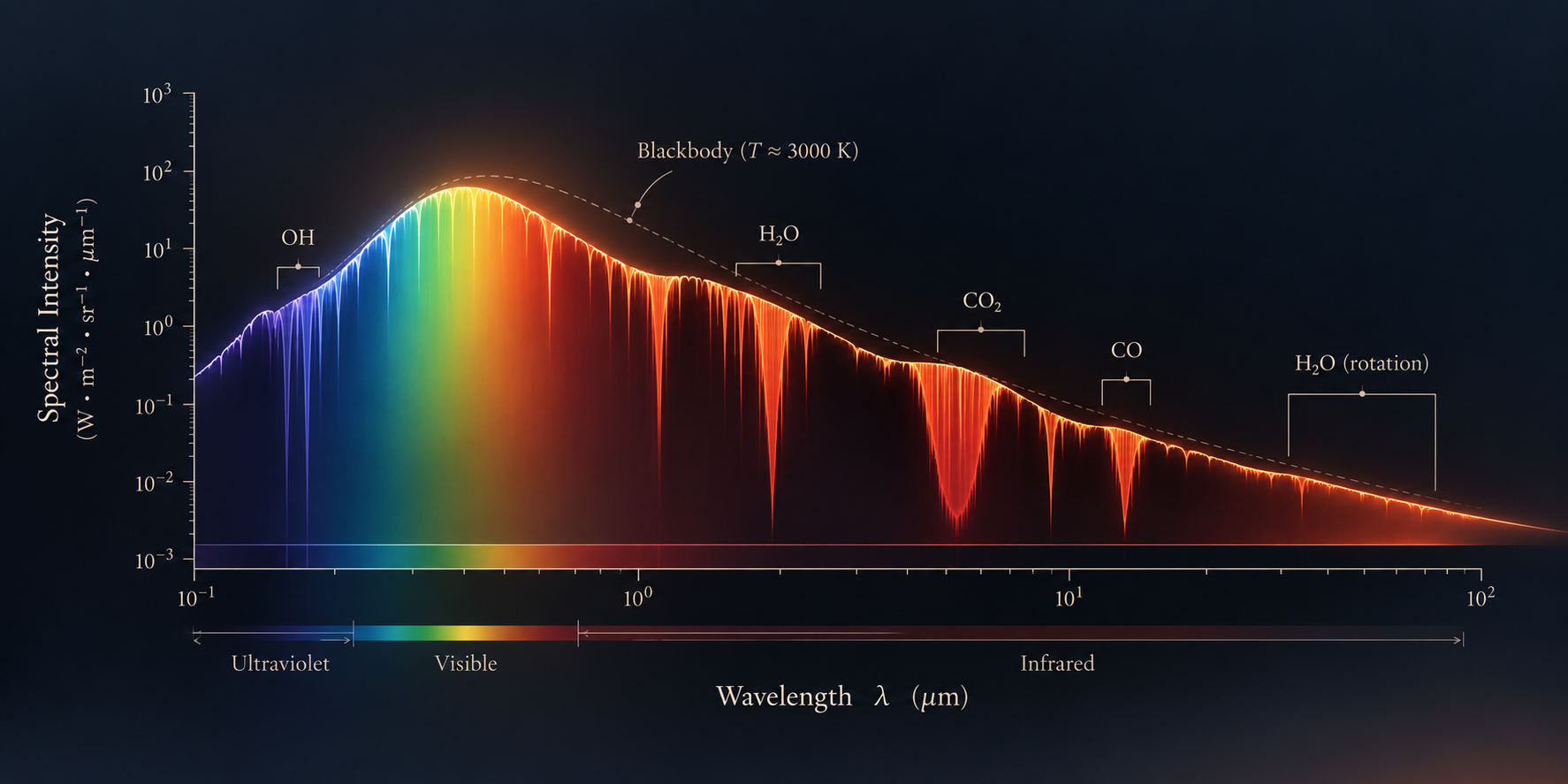
Radiative intensity describes energy travelling in a particular direction. Its spectral form, , also resolves wavelength. For a blackbody, the spectral intensity follows Planck’s law. Using vacuum wavelength and taking the refractive index as approximately unity,
where is Planck’s constant, is the speed of light in vacuum, is Boltzmann’s constant, and is wavelength. Integrating over wavelength and the outward hemisphere gives the total blackbody emissive power:
The factor comes from integrating the direction-independent blackbody intensity with the projected-area weighting over a hemisphere. This distinction matters: intensity and heat flux have different units and cannot be substituted directly for one another. NIST’s optical-radiation metrology material presents the spectral-radiance form of Planck’s law.
For a diffuse real surface, spectral emissivity relates its emitted intensity to the blackbody value:
A gray-surface approximation treats emissivity as independent of wavelength, giving . Combustion gases need a different treatment: their emission and absorption can vary sharply with wavelength, and the radiation emerging from a gas volume also depends on the distance travelled through it. A single surface-emissivity value does not describe that transport.
Imagine following a narrow ray through the chamber. Along its path, four processes can change its intensity: emission adds radiation, absorption removes it, scattering redirects radiation out of the ray, and scattering from other directions adds radiation into it. With local thermodynamic equilibrium, the steady radiative transfer equation can be written as
Here is distance along the ray, and are absorption and scattering coefficients in , and describes the angular distribution of scattering. The phase function is normalized so that its integral over outgoing directions is . Emission and in-scattering contribute positively; absorption and out-scattering contribute negatively. IUPAC’s definition of the RTE describes this balance.
For a gas-only model of combustion products such as water vapour and carbon dioxide, molecular scattering of thermal radiation is commonly neglected. This assumption needs reconsideration when particles or droplets contribute significantly. Neglecting scattering leaves both emission and absorption:
Over a short distance , absorption removes , while emission adds . Under local thermodynamic equilibrium, Kirchhoff’s law connects the absorption coefficient to the thermal emission source. This is the same non-scattering form given in NIST’s radiation formulation, Section 3.3.
Defining optical depth along the path as
the solution becomes
The first term is radiation entering the path and surviving attenuation. The second adds emission from the gas along the path, with each contribution attenuated before reaching the observation point. For an isothermal gas, it simplifies to
This gives a physical meaning to optical thickness. At small optical depth, much of the incoming radiation passes through. At large optical depth, the emerging intensity approaches the local blackbody intensity for that wavelength in an isothermal gas. A mixture can be optically thick in some spectral bands and relatively transparent in others.
Radiation is therefore nonlocal: what reaches the wall depends on conditions along the paths through the chamber. Local energy conservation still applies, but a local temperature and its gradient do not fully determine the radiation field. In three dimensions, the steady spectral intensity depends on three spatial coordinates, two direction angles, and wavelength. A transient description adds time.
The wall heat flux follows from the intensity arriving from the gas. Let the wall normal point into the gas, so incoming directions satisfy . The spectral irradiation is
For an opaque, diffuse wall with spectral absorptivity equal to emissivity, the net radiative heat flux into the wall is
Under a gray-wall approximation, this becomes , where is total irradiation. The wall absorbs part of the incoming radiation and emits radiation of its own. Its reflected radiation also affects the surrounding radiation field and must be included in the boundary conditions. Idaho National Laboratory’s heat-transfer documentation explains this connection between intensity, irradiation, and wall exchange.
For a wall model including these two hot-gas heat-transfer mechanisms,
Both contributions depend on the wall temperature. In a regenerative cooling calculation, that temperature must also be consistent with conduction through the wall and heat removal by the coolant. Adding radiation therefore changes a coupled thermal problem.
The remaining difficulty is the gas spectrum. Molecular transitions produce many absorption and emission lines, and resolving them individually across a chamber can be expensive. For my preliminary design program, I use a weighted-sum-of-gray-gases model, or WSGG, with coefficients from Fabiani’s rocket-radiation work. It represents the spectral behaviour using a small set of weighted gray components; these are mathematical components, rather than separate chemical species. The coefficient ranges and the approximation used for radiation transport still matter. Fabiani’s thesis provides the research basis for that choice.
In part 2, I will explain how I implemented that model, the assumptions made when applying it to the thrust chamber, and how the radiation term enters the wall-temperature and coolant-energy calculations. The comparison I want to make is straightforward: with the engine inputs held consistent, how much does including radiation change the predicted heat load and wall temperature?